Table Of Content

The green screws are for the ground wires, the silver/stainless colored screws are for the white neutral wires and the brass colored screws are for the black “hot” wires. As we see in the following Basement Wiring Diagram, the square patterns are switches while the circular or rectangular patterns are light fixtures. A simple wiring diagram shows the connections in series and parallel for the various electrical appliances such as bulbs. Different sections colored in different colors here do not represent the color coding of wires.
Residential Electrical Wiring
Look at the picture and find the wires coming off the device. The movement sensor will have some wires that go to a transformer, and others to HVAC equipment and lights. Wiring diagrams are often easier to interpret than written directions, especially for people unfamiliar with electrical systems and concepts. If you can take your finger and trace a line from one place to another, you can follow a wiring diagram.
Push the Wires into the Box
What is WiFi mesh & how does it work? - Singtel
What is WiFi mesh & how does it work?.
Posted: Fri, 04 Aug 2023 06:35:45 GMT [source]
The difference, we could say, is that now the red wire switching light C6 is "flowing" in the same direction as the other wires that extend power further out, whereas the red for light B5 "came back from" switch C5. This (row 6) sub-branch ends with receptacle D6 receiving power, with no one to send it on to, except of course to whatever is plugged into it. A3 needs to get its hot and neutral connections passed on so that two lights (A1 and B1) can burn -- not all the time, but according to what the switches at A2, B2, and C2 say. A2 is a normal single-pole switch, as seen by its two side screws. According to the position of its handle, it will either let its light (A1) get the hot connection or not; the neutral connection at A2 (a wire connector) is not affected by the switch.

Hot Product
Modern receptacles are called “duplex receptacles” because they have two screws on both sides. As the name implies, they can bring electrical current into one set of screws and then send it out on the other “duplex” set of screws to another fixture. Light switches and wall outlets have screws on both sides for connecting wires.
This circuit starts with A4 receiving hot (black) and neutral (white) wires from the main electrical panel -- imagine the panel below the image. A4 passes hots and neutrals to nearby receptacles A3 and A5 by means of their wires' contact with the terminals on A4. A3 and A5 are the beginnings of the two main branches of this circuit, and we can identify several sub-branches that are developed beyond them.
Heart: Anatomy & Function - Cleveland Clinic
Heart: Anatomy & Function.
Posted: Fri, 26 Jan 2024 08:00:00 GMT [source]
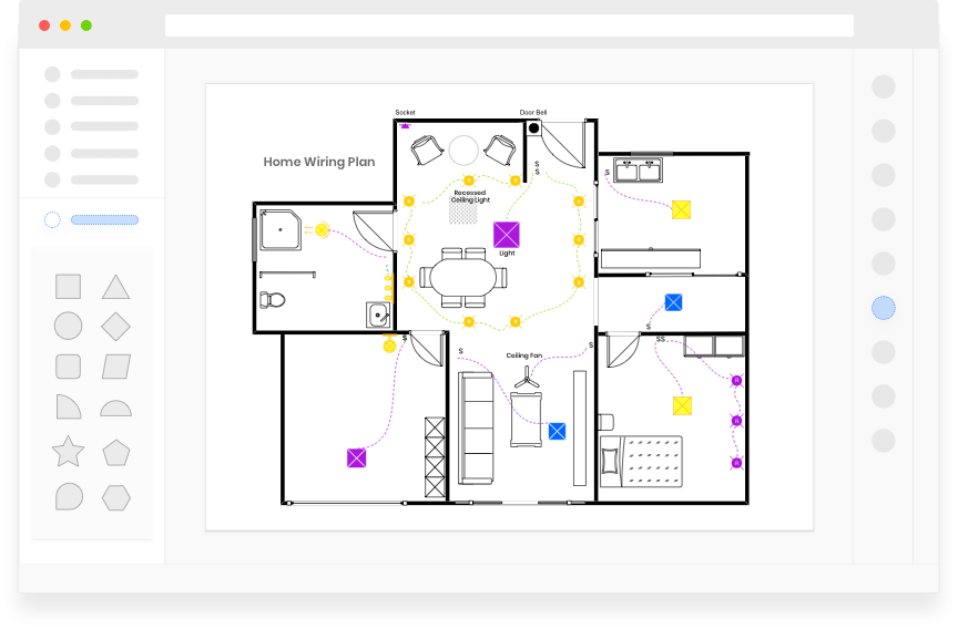
The neutral point of an electrical wiring circuit is typically connected to the ground. House wiring diagrams are graphical representations of the electrical connections and layout of a house. They provide a visual guide for electricians and homeowners to understand the electrical system and its components. These diagrams illustrate the location of circuit breakers, outlets, switches, and other electrical devices, as well as the wiring routes and connections.
The light will be controlled by switch B4, D2 and D3 by switch C3, and D1 by switch C1 (switched receptacles!). And, yes, a white wire is being used as a hot down to B4; that's the way a cable of two wires comes -- black and white. For some time now this white should be colored differently when installed. In fact wiring done under the 2011 NEC code should use 3- not 2-conductor cable to provide a neutral for possible special switches. The heavier the gauge, i.e., the thicker the copper wire, the more electrical current it can carry without overheating.
Wiring diagrams also apply to internal wiring, like a circuit board inside a computer or washing machine. Have a DIY electrical project but find wiring diagrams confusing? Take them step by step, and soon you'll be wiring like a pro. 4 Repeat this process, switching on room lights one by one, and note the circuit breaker that controls each set of lights. Once Gallant starts wiring a house, virtually every aspect of his work is controlled by codes, both local and national. These codes are the final word on safe installation practices.
The diagram is not meant as a guide for doing wiring; for example, the white wires connected to some switches here should nowadays be taped red or black. The diagram is more to familiarize you with what you may encounter in existing homes. Light switches simply serve to disrupt, or “break,” the flow of electricity in the wiring before it gets to the light fixture. This interruption in the flow is what turns the light off, and then back on.
Gallant is meticulous in adhering to them, yet he often goes a step further to make his electrical systems even safer and easier to use. On the following pages, you’ll see the basics of wiring a house to meet code, along with a look at Gallant’s extras. It is the place where we go through the steps you need to take to create a house wiring diagram with EdrawMax. However, before we start, there are a few things you need to know about the interface. Homeowners doing DIY electrical work are most likely to go with basic wiring and pictorial diagrams, usually included in the instructions for electrical devices. This could be the power supply or the light or sensor that you’re installing.
Diagrams showing electrical flow through a circuit use standardized symbols to represent electrical components. Ground is a vertical line with three successively smaller horizontal lines underneath. Switches are diagonal lines emanating from the line representing the electrical flow. But when I was a second-year apprentice and my foreman handed me a wiring diagram, I briefly panicked. I saw a bunch of boxes and a lot of seemingly randomly drawn lines.
Within these articles you will find some of the most common questions homeowners ask about switches. One of the key benefits of house wiring diagrams is that they help in troubleshooting electrical issues. By referring to the diagram, electricians can easily identify and fix any problems or faults in the wiring system. A home’s electrical system is designed to work off 120 volts with the exception of certain major appliances, such as an electric clothes dryer, which runs off 240 volts. So the neutral from B5 ties through box C5 to give D5 its neutral connection.
Determine which major electrical appliance(s) it supplies by turning on each electrical appliance (don’t forget equipment such as the furnace and the pool pump) until you find the right one(s). Repeat with the other large circuit breakers and major appliances. 1 At the electrical panel, turn off all of the circuit breakers. Many states and local jurisdictions permit homeowners to perform their own electrical work, but some do not.
It also helps in troubleshooting electrical issues by pinpointing the location of a problem.Additionally, a House Wiring Schematic Diagram provides convenience. Have you ever tripped a circuit breaker and had to search for the specific one to reset? With a diagram, you can easily locate the breaker and know which part of the house it controls. This saves time and eliminates guesswork.Moreover, the diagram serves as a future reference for any changes or upgrades in the electrical system. It promotes safety, convenience, and future planning, making it a valuable asset to every homeowner.
Imagine walking into your newly built dream home, excited to finally see all of your ideas come to life. As you enter the living room, you notice something on the wall that catches your eye. It's a detailed diagram, almost like a blueprint, with lines and symbols indicating the wiring of your house. It shows the layout of wires, outlets, switches, and other electrical fixtures, providing a clear understanding of how the electricity flows through your home.